TI MSP432 ToF 3D Space Scanner
Apr 17, 2023
Project Title: TI MSP432 ToF 3D Space Scanner
Project Overview
This project is an embedded spatial measurement system built around a TI MSP432E401Y SimpleLink microcontroller, a rotating time-of-flight distance sensor, and a stepper motor. The scanner captures a 360-degree vertical slice, sends distance data to a PC over UART, and reconstructs the measured space as an XYZ point cloud and wireframe model with Python and Open3D.
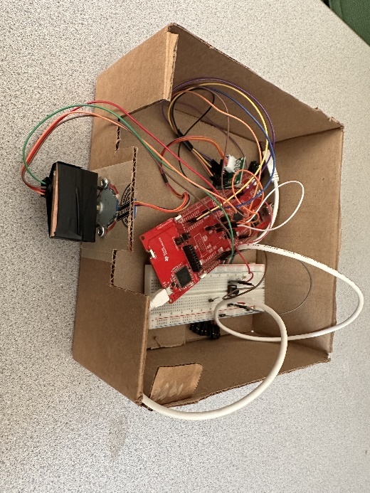
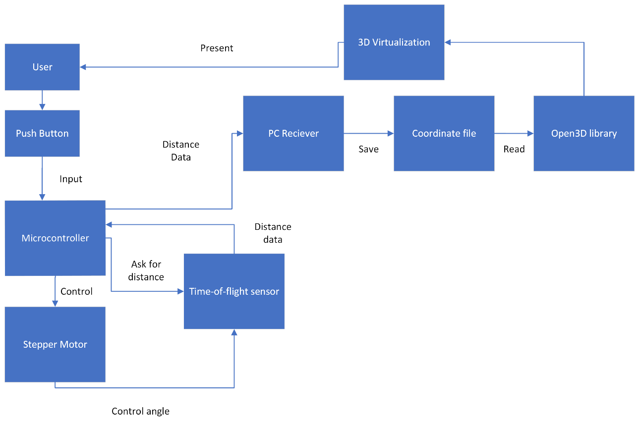
The hardware produces one full circular scan by rotating the ToF sensor in 11.25-degree increments. Each stop produces a distance reading in the y-z plane. After each full rotation, the system can be moved forward along the x-axis by a fixed increment so multiple slices can be joined into a simple 3D reconstruction.
Objectives
- Low-Cost Spatial Scanning: Build a functional scanner from a microcontroller board, breadboard circuit, stepper motor, ToF sensor, and simple enclosure.
- Precise Angular Sampling: Use stepper-motor control to collect 32 evenly spaced measurements per full rotation.
- Embedded Sensor Interface: Connect the ToF sensor to the MSP432 over standard-mode I2C and stream readings to a PC over UART.
- Coordinate Reconstruction: Convert polar distance readings into XYZ coordinates for 3D visualization.
- System Integration: Combine active-low user input, motor control, sensor measurement, serial communication, and Open3D rendering into one workflow.
Hardware and Communication Stack
The system centers on the MSP432E401Y running at a 120 MHz core clock. The ToF sensor communicates with the microcontroller over I2C at 100 kbps, while the PC receiver reads scan output over UART at 115200 bits/s with 8 data bits, one stop bit, and no parity.
The prototype uses:
- Microcontroller: TI MSP432E401Y SimpleLink development board
- Distance Sensor: Time-of-flight sensor using a 940 nm light pulse for ranging
- Motion Control: Stepper motor driven from MSP432 port
PH0throughPH3 - Sensor Bus: I2C
SCLonPB2andSDAonPB3 - User Input: Active-low push button on
PM0 - Visualization Host: PC-side Python receiver using PySerial and Open3D
- Power: 3.3 V for the sensor/button circuit and 5 V for the stepper motor path

360-Degree Scan Workflow
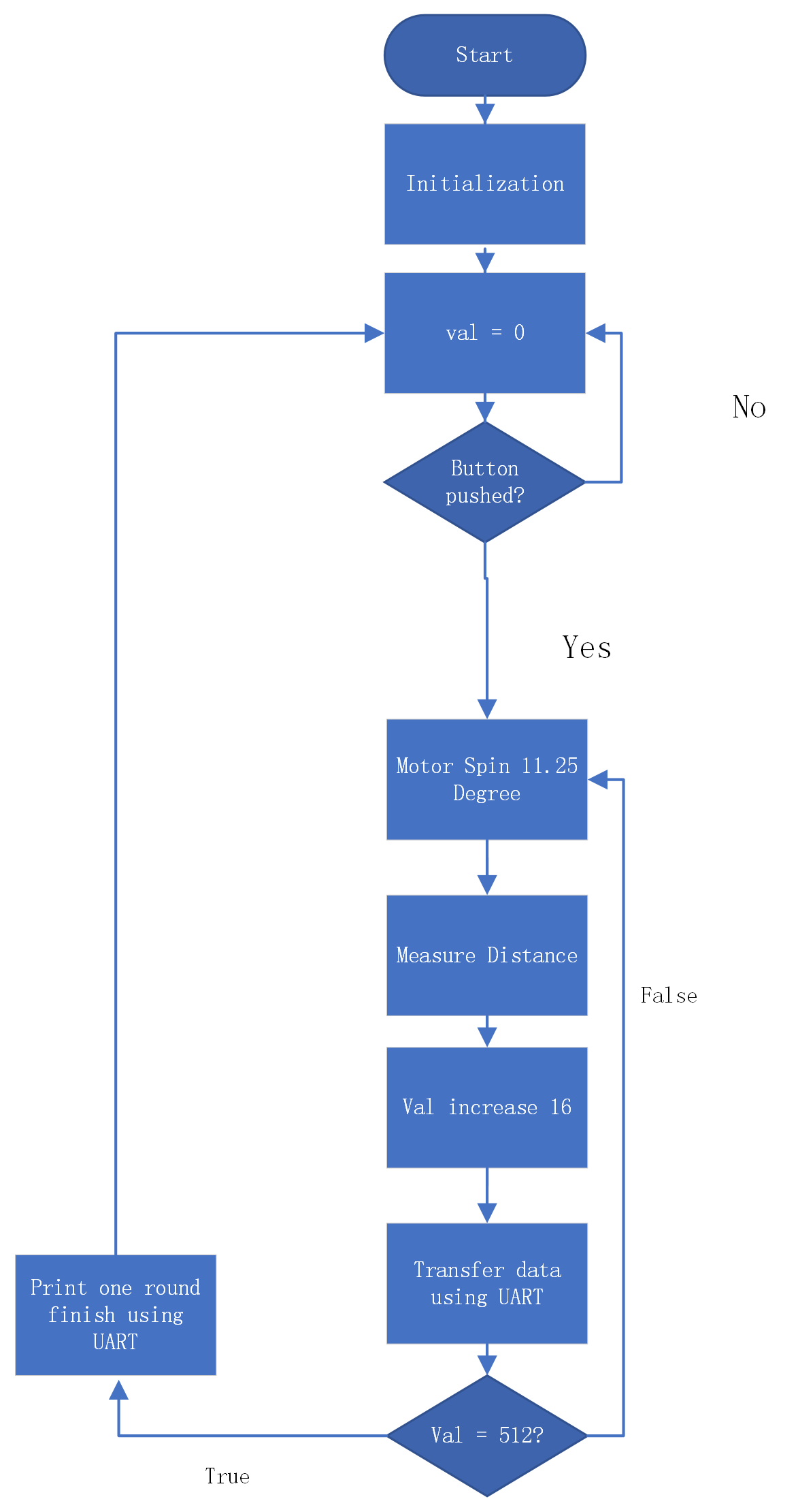
When the PC receiver is ready and the microcontroller firmware is running, the user presses the active-low push button to start a scan. The stepper motor rotates the ToF sensor counterclockwise through one full revolution. A complete rotation is 512 motor steps, and the firmware records one measurement every 16 steps, producing 32 measurements per round.
At each measurement point:
- The firmware waits for the ToF sensor data-ready signal.
- The microcontroller reads the range value over I2C.
- The firmware forwards the range data to the PC over UART.
- The stepper motor advances to the next 11.25-degree position.
The motor uses a full-step drive pattern for stronger torque. In the final report estimate, each motor step consumes about 40 ms because each phase switch uses a 10 ms delay. With the ToF timing budget included, a full scan round takes about 21.5 seconds.
UART, Python, and Open3D Pipeline
The PC-side receiver listens to the UART stream, extracts the measured distance, and converts each polar reading into Cartesian coordinates. The scanner treats each reading as a distance vector in the y-z plane:
y = distance * cos(angle)
z = distance * sin(angle)
angle = n * -11.25 degrees
The receiver writes the resulting coordinates into an XYZ file. The x-coordinate is controlled by the scan round: after a full rotation, the user can move the scanner by a fixed x increment and continue with the next slice. In the final report example, the x increment was 500 mm.
Open3D then reads the XYZ file to render:
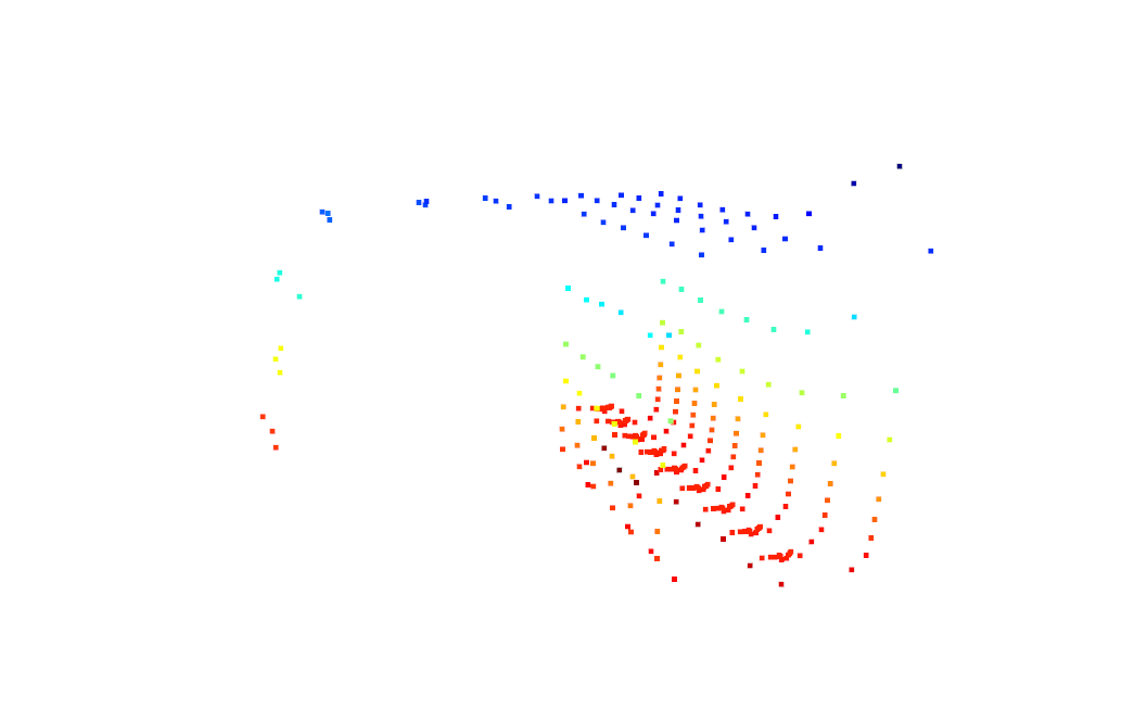
- a point cloud of the measured samples
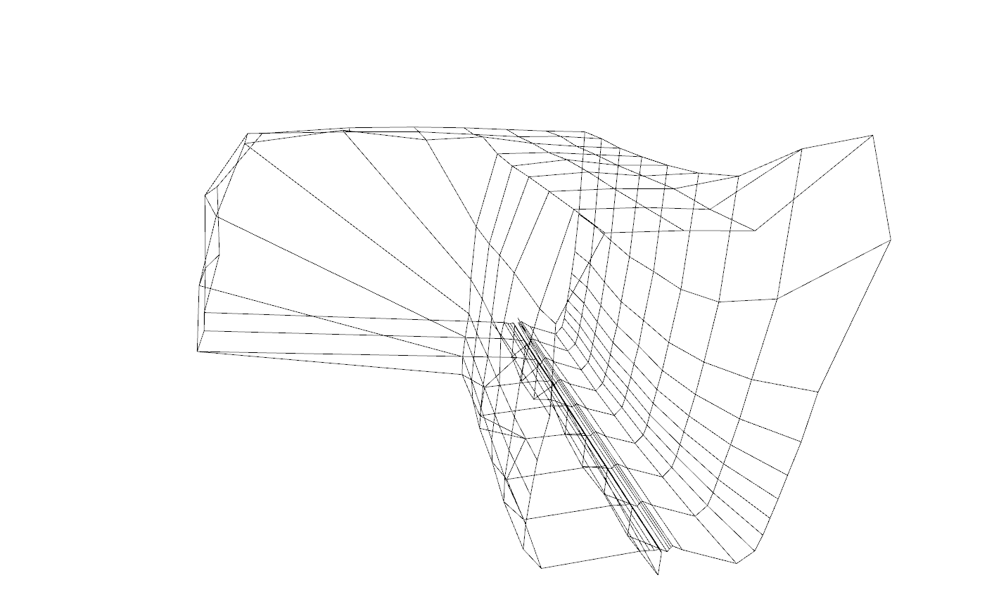
- a line-connected model that joins each 32-point slice
- connections between slices along the x-axis
Hallway Scan Result
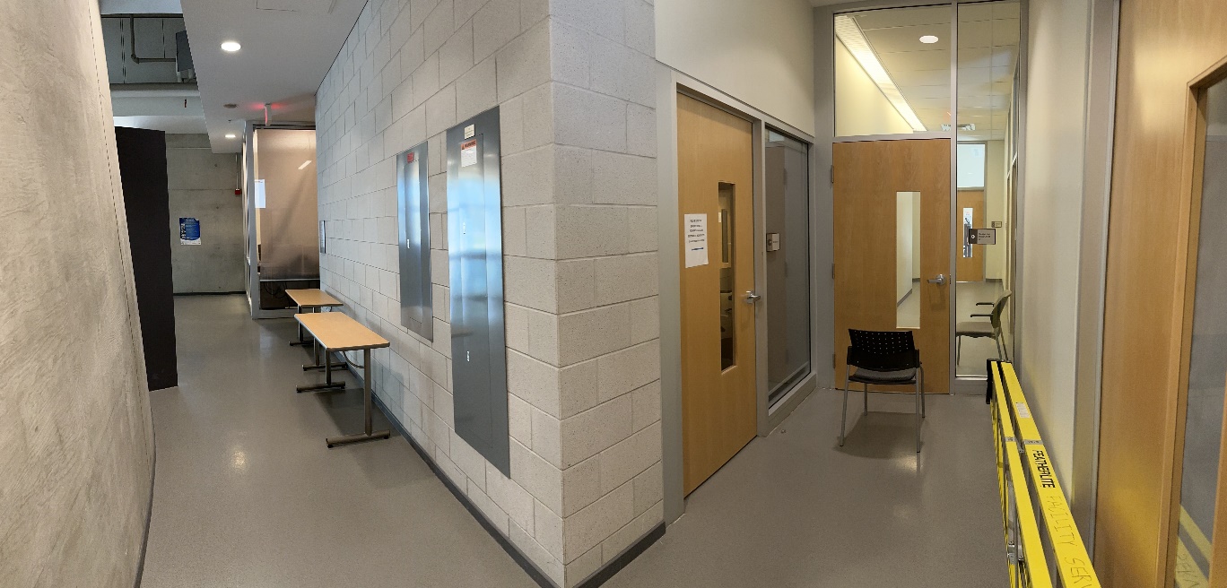
The application example scanned a hallway corner. The final run used nine scan rounds, each with 32 measurements, for a total of 288 coordinate points. The reconstruction captured the 90-degree walkway turn and produced both point-cloud and wireframe outputs.
Limitations and Engineering Tradeoffs
The project was intentionally simple, which made the full data path understandable but introduced clear limits:
- Fixed x-axis movement: The scanner is not a continuous real-time mapper. Each 3D reconstruction depends on manually moving the device by a known x increment between scan rounds.
- Angular resolution: The example uses 11.25-degree spacing, which is enough to show the hallway turn but too coarse for precise surface reconstruction.
- ToF range sensitivity: The sensor has a 1 mm resolution, but practical ranging error depends on lighting, target reflectance, and distance. The final report used a 25 mm ambient-light ranging error as the main accuracy term.
- Computation placement: Trigonometry and Open3D reconstruction are handled on the PC side rather than on the MSP432, avoiding unnecessary floating-point and visualization load on the microcontroller.
- Speed bottlenecks: Stepper motion delay and ToF timing dominate scan time more than UART throughput.
Outcomes
- Built a working embedded 3D scanning prototype with a rotating ToF sensor and stepper motor.
- Integrated active-low button control, I2C sensor reads, UART streaming, and PC-side coordinate conversion.
- Captured 32 measurements per revolution and chained multiple scan rounds into a simple 3D reconstruction.
- Generated Open3D point-cloud and wireframe views from real hallway measurements.
- Identified practical limits in angular resolution, ToF error, fixed-increment scanning, and scan speed.
Why It Matters
This project is a compact example of hardware-software integration. The interesting part is not any single component by itself, but the full path from physical motion to sensor measurement to serial protocol to coordinate reconstruction.
It also shows a useful embedded-systems design instinct: keep the microcontroller responsible for deterministic hardware control and data acquisition, then move heavier visualization and floating-point processing to the PC where the tooling is stronger.